Bunjour,
je poste ce en anglais car il est beaucoup trop complexe pour moi d'expliquer clairement en français, j'espère que vous ne m'en voudrez pas!
The passive crossover filters used in the TAD and Rey Audio (Kinoshita) monitors are all very similar, in their layout and basic functioning, to the TN-2 model used in the TAD TSM-2 (= Exclusive 2402):
TAD TN-2
The schematic is:

This filter consists of:
- 6th order Low Pass on the Woofer (in a semi-balanced topology, i.e. the first inductance is split in two halves and placed on either branch of the filter, and the following two inductors and placed on either branch),
- 2nd order High Pass on the compression driver+horn,
- plus impedance correction (Zobel on Woofer and series RLC on horn), and an equalization contour (parallel RLC) and L-Pad attenuation on the horn.
The purpose of the asymmetrical slopes (6th/2nd) is to compensate for the physical offset between the acoustic centres (based on the technical drawings of the TSM-2, the driver's diaphragm is ~33 cm behind the base of the woofer cone).
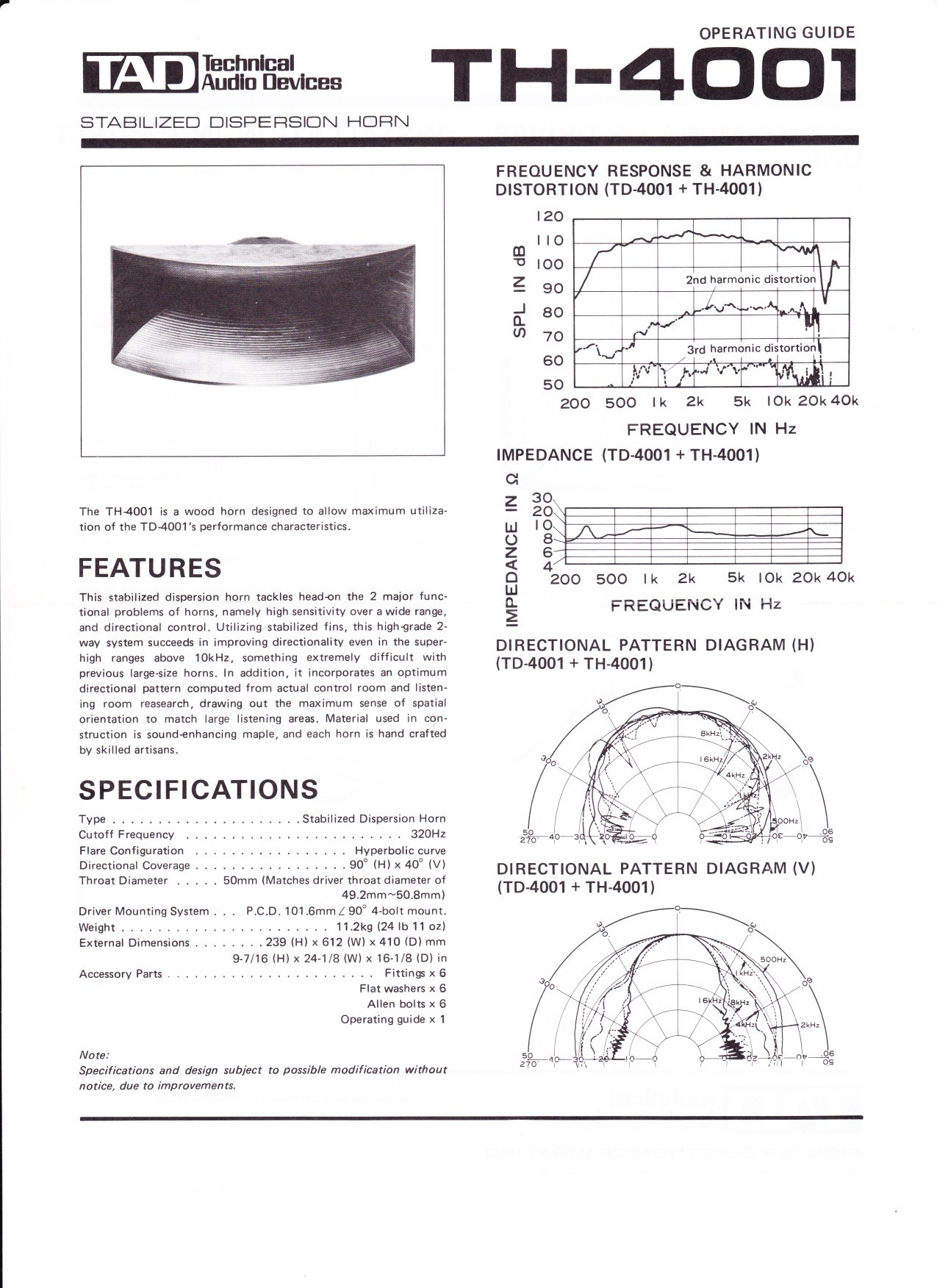
It should also be noted, though, that the TH-4001 horn itself imposes a steep (> 4th order) high-pass in the vicinity of its cut-off frequency (Fc = 320 Hz), which means that it is actually impossible to obtain a true 2nd (or 3rd, or even 4th) order high-pass transfer function. The resulting high-pass is instead the combination of the electrical high-pass (2nd order) with the intrinsic acoustical high-pass happening approximately one octave below that (>4th order).
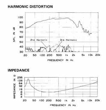
Having said that, based on the official published frequency response curves of the TL-1601a woofer and the TD-4001+TH-4001 driver+horn combo:
AND using the filtered responses as targets:
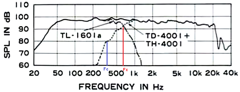
it is possible to reverse-engineer the passive crossover filter and obtain the correct L, C, and R values to employ:
Low-Pass Woofer (6th ord. Linkwitz-Riley @ 650Hz)
L1 = L4 = 1.6 mH; C1 = 56 μF; L2 = 3.0 mH; C2 = 33 μF; L3 = 1.5 mH; C3 = 6.8 μF
Zobel (impedance comp. Woofer)
C4 = 20 μF; R1 = 8.2 Ohm
High-Pass Horn (2nd ord. Q = 0.9 @ 1.31 * 650 = 850 Hz)
C1+C2+C3 = 10+10+3.3 = 23.3 μF; L1 = 2.2 mH
Fixed L-Pad (-10dB)
R1 = 5.6 Ohm; R2 = 3.3 Ohm
parallel RLC (equaliz. horn)
C4+C6 = 15+15 = 30 μF; L2 = 0.2 mH; R3 = 3.3 Ohm
series RLC serie (impedance comp. horn)
C5 = 15 μF; L3 = 1.1 mH; R4 = 22 Ohm
Here are the modelled results of the application of these values to the individual speaker units:

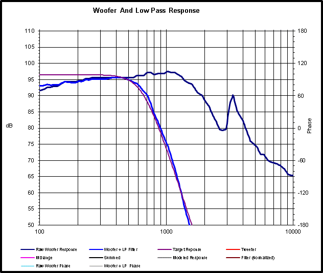


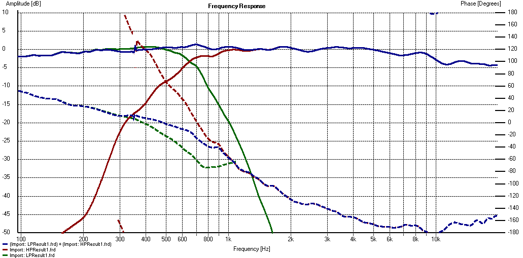
And the resulting simulated crossover, with the offset adjusted to 33cm:
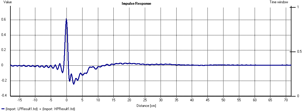
And the associated Impulse Response:
I hope this helps 'demistify' this famous crossover!
Cheers,
Marco
je poste ce en anglais car il est beaucoup trop complexe pour moi d'expliquer clairement en français, j'espère que vous ne m'en voudrez pas!
The passive crossover filters used in the TAD and Rey Audio (Kinoshita) monitors are all very similar, in their layout and basic functioning, to the TN-2 model used in the TAD TSM-2 (= Exclusive 2402):
TAD TN-2
The schematic is:
This filter consists of:
- 6th order Low Pass on the Woofer (in a semi-balanced topology, i.e. the first inductance is split in two halves and placed on either branch of the filter, and the following two inductors and placed on either branch),
- 2nd order High Pass on the compression driver+horn,
- plus impedance correction (Zobel on Woofer and series RLC on horn), and an equalization contour (parallel RLC) and L-Pad attenuation on the horn.
The purpose of the asymmetrical slopes (6th/2nd) is to compensate for the physical offset between the acoustic centres (based on the technical drawings of the TSM-2, the driver's diaphragm is ~33 cm behind the base of the woofer cone).
It should also be noted, though, that the TH-4001 horn itself imposes a steep (> 4th order) high-pass in the vicinity of its cut-off frequency (Fc = 320 Hz), which means that it is actually impossible to obtain a true 2nd (or 3rd, or even 4th) order high-pass transfer function. The resulting high-pass is instead the combination of the electrical high-pass (2nd order) with the intrinsic acoustical high-pass happening approximately one octave below that (>4th order).
Having said that, based on the official published frequency response curves of the TL-1601a woofer and the TD-4001+TH-4001 driver+horn combo:
AND using the filtered responses as targets:
it is possible to reverse-engineer the passive crossover filter and obtain the correct L, C, and R values to employ:
Low-Pass Woofer (6th ord. Linkwitz-Riley @ 650Hz)
L1 = L4 = 1.6 mH; C1 = 56 μF; L2 = 3.0 mH; C2 = 33 μF; L3 = 1.5 mH; C3 = 6.8 μF
Zobel (impedance comp. Woofer)
C4 = 20 μF; R1 = 8.2 Ohm
High-Pass Horn (2nd ord. Q = 0.9 @ 1.31 * 650 = 850 Hz)
C1+C2+C3 = 10+10+3.3 = 23.3 μF; L1 = 2.2 mH
Fixed L-Pad (-10dB)
R1 = 5.6 Ohm; R2 = 3.3 Ohm
parallel RLC (equaliz. horn)
C4+C6 = 15+15 = 30 μF; L2 = 0.2 mH; R3 = 3.3 Ohm
series RLC serie (impedance comp. horn)
C5 = 15 μF; L3 = 1.1 mH; R4 = 22 Ohm
Here are the modelled results of the application of these values to the individual speaker units:
And the resulting simulated crossover, with the offset adjusted to 33cm:
And the associated Impulse Response:
I hope this helps 'demistify' this famous crossover!

Cheers,
Marco


